Why Choose a Horizontal Screw Conveyor for Bulk Handling?
Moving powders, granules, and small bulk solids requires more than a motor and a rotating shaft. Material behavior changes with moisture, particle size, temperature, and flow rate. A horizontal screw conveyor offers a controlled, enclosed path for many routine conveying duties. Its compact layout can fit beneath hoppers, mixers, storage bins, and packing lines. Operators can also inspect access points without exposing the entire transfer route.
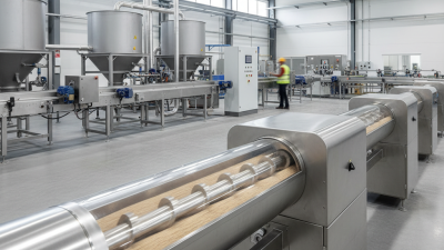
The design is straightforward. A helical flight rotates inside a trough or tubular casing, pushing material toward the discharge point. This action supports steady feeding over short and medium distances. It can also reduce dust escape when seals and covers are selected correctly. In real facilities, I have seen the best results come from matching screw speed, pitch, trough design, and motor capacity to the material. A dense powder needs different handling from dry grain or fragile pellets. Guesswork becomes expensive.
No conveyor is perfect. High speeds may increase particle damage, heat, or wear. Sticky products can build on flights, while abrasive solids can shorten component life. These risks deserve attention before purchase. A practical selection process reviews bulk density, moisture, temperature, capacity, incline, cleaning needs, and maintenance access. Manufacturers should provide load calculations, material recommendations, and clear service guidance. Reliable performance depends on the whole system, not one machine. When properly specified, a horizontal screw conveyor can deliver consistent movement, simple control, and sensible long-term value for bulk handling operations.
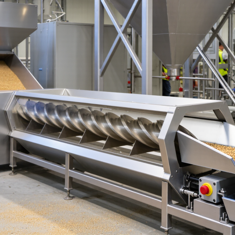
A horizontal screw conveyor moves bulk material steadily through a trough. Its compact layout suits plants with limited headroom or short transfer distances. ANSI/CEMA 350 provides a common framework for describing screw conveyor components, dimensions, capacities, and selection practices. This framework helps engineers compare designs using consistent terms. It also supports clearer communication between equipment users, fabricators, and maintenance teams.
The standard encourages careful review of screw diameter, pitch, shaft arrangement, trough design, speed, and material loading. Material properties matter just as much. Moist powder behaves differently from dry grain or abrasive minerals. A reliable design considers bulk density, moisture, temperature, particle size, and flowability. Small details count. For example, an unsuitable hanger can increase resistance and create buildup around the bearing.
Horizontal conveyors often offer simple access and predictable discharge control. They can also require less vertical lifting than inclined systems. However, ANSI/CEMA 350 is a design guide, not a substitute for field verification. Actual conditions may expose problems that calculations miss. Sticky material, irregular feeding, or unexpected surges can change performance quickly. That is where practice gets less tidy. Reviewing operating data, checking clearances, and inspecting wear points remain essential before final equipment selection.
A horizontal screw conveyor suits bulk handling when steady, controlled movement matters. Its performance depends on trough loading, screw speed, pitch, and material behavior. Trough loading describes the cross-sectional space occupied by bulk solids. Practical sizing often compares 15%, 30%, and 45% loading levels. A 15% load leaves space for free-flowing powders or materials that may surge. At 30%, capacity rises, but torque and friction require closer attention. The 45% level can support high throughput for suitable, consistent materials. It is not a universal target.
A capacity estimate combines screw diameter, rotational speed, pitch, loading percentage, and bulk density. Yet bulk density changes with moisture, particle size, and compaction. That detail matters. Dry granules may move calmly at 30% loading, while damp material can bridge or cling to the trough. Operators should check motor current, bearing temperature, discharge consistency, and buildup along the flight edges. These signals can reveal overloading before a stoppage occurs. Not always.
Horizontal conveying reduces elevation demand and may simplify feeding between process stages. Still, higher loading does not automatically improve operating costs. It can increase startup torque, wear, and cleaning time. A neat calculation can mislead. Confirm the design with representative material tests, measured bulk density, and realistic operating hours. Leave a margin for seasonal changes and uneven feeding. Uneven feeding can quickly turn a 45% design into an unstable process.
A horizontal screw conveyor gives bulk materials a steady, enclosed path. Its real advantage appears when speed stays controlled, usually around 20–100 RPM. At this range, operators can match conveying action to particle size, moisture, and fragility. CEMA’s Screw Conveyors for Bulk Materials handbook explains that speed, loading, pitch, and flight design must work together. RPM alone is not a guarantee.
Lower, stable speed reduces sudden flight impact and unnecessary turbulence. That can help protect flakes, pellets, powders, and coated granules from chipping or smearing. It also limits air movement that lifts fine particles near transfer points. The U.S. Chemical Safety Board documented 281 combustible-dust incidents between 1980 and 2011, causing 119 deaths and 718 injuries. Dust control matters. It is process discipline.
In practice, I would begin near 20 RPM for fragile or dusty products, then increase gradually toward 100 RPM. Watch motor load, bearing temperature, dust around seals, and particle shape. A simple sample check helps. One caution remains: slow conveying can increase residence time, buildup, or plugging when moisture rises. OSHA’s Combustible Dust National Emphasis Program recommends controlling dust accumulation and ignition sources. The best setting is measured, documented, and occasionally questioned.
Why Choose a Horizontal Screw Conveyor for Bulk Handling?
For 30–60 metre horizontal runs, a screw conveyor offers controlled movement in a compact, enclosed path. Its rotating flight pushes powder, granules, or small solids through a trough or tubular housing. In practical plant assessments, this design often requires less floor space than a belt system. It also avoids the high air consumption associated with pneumatic conveying. Dust control can be simpler when seals and extraction points are correctly maintained.
Pneumatic systems can move material around obstacles and through elevated routes. However, they usually demand more energy, and high air velocity may damage fragile particles. Long belt conveyors can be efficient over 60 metres, especially with large capacities. They need careful tracking, tension control, loading zones, and multiple transfer points. Each transfer point can create dust, spillage, or material degradation. Belts also require more open access, which may complicate sanitation or enclosure design.
The screw conveyor has limits. Product friction can increase motor load, especially with sticky or poorly flowing material. Flight wear may become noticeable near the feed point. That assumption can fail. A single screw is not automatically the best choice for every product. Moisture, bulk density, temperature, capacity, and cleaning requirements should guide the selection. In one assessment, a slightly slower screw system proved more stable because it reduced surging and prevented uneven discharge. Small details matter. There is no perfect layout.
| Comparison Dimension | Horizontal Screw Conveyor 30–60 m run |
Pneumatic Conveying System 30–60 m route |
Belt Conveyor 30–60 m run |
|---|---|---|---|
| Best-fit application | Controlled, enclosed transfer of powders, granules, and small particles over a fixed horizontal route. | Flexible routing, multiple discharge points, elevation changes, or areas where mechanical conveying is difficult to install. | High-throughput transport of relatively free-flowing bulk solids over a fixed route. |
| Typical conveying capacity | Approximately 5–100 m³/h, depending on screw diameter, speed, fill level, material density, and inclination. | Approximately 1–50 t/h for many dilute-phase applications; capacity varies significantly with air velocity, pressure, pipe diameter, and material properties. | Approximately 50–500+ t/h for many industrial layouts; capacity depends on belt width, speed, loading profile, and bulk density. |
| Energy demand per tonne | Typically about 0.5–2.0 kWh/t for horizontal service, excluding auxiliary equipment; actual demand rises with friction, fill level, and material resistance. | Typically about 2–10 kWh/t in dilute-phase service because compressors or blowers must move both air and solids. | Typically about 0.1–0.4 kWh/t for a horizontal installation, making it generally the most energy-efficient option at high throughput. |
| Space and layout | Compact plan area and enclosed construction; long runs may require intermediate hanger bearings and access points. | Small pipe footprint and highly flexible routing, but requires space for blowers, filters, airlocks, and receiving equipment. | Requires a clear corridor, structural supports, loading and discharge zones, and adequate access along the belt. |
| Material containment | Fully enclosed trough or tubular housing can limit dust release and protect the product from external contamination. | Enclosed throughout the route; suitable for dusty materials when filters, seals, and pressure controls are correctly designed. | Open belts may generate more dust or product loss; covered or enclosed designs improve containment but add cost and access requirements. |
| Material handling characteristics | Well suited to powders, granules, flakes, and mildly cohesive materials; shear can affect fragile or friable products. | Suitable for many powders and granules, but air velocity and bends can cause attrition, segregation, or degradation. | Gentle handling is possible at suitable belt speeds; very fine, sticky, or highly cohesive materials may require special belt and transfer designs. |
| Long-run suitability | Practical for 30–60 m when shaft torque, hanger-bearing spacing, alignment, wear, and cleanout requirements are properly engineered. | Technically suitable for 30–60 m and longer, but pressure loss and air-system power increase with distance, bends, and solids loading. | Highly suitable for 30–60 m horizontal routes, particularly when continuous high capacity and low operating cost are priorities. |
| Maintenance requirements | Inspect bearings, seals, flighting, shaft alignment, and drive components; intermediate hanger bearings require planned access and lubrication where applicable. | Maintain blowers, filters, rotary valves, diverter valves, pipelines, seals, and wear sections; leaks can reduce performance quickly. | Inspect belt tracking, idlers, pulleys, scrapers, splices, and tension; moving components are distributed along the conveyor. |
| Noise profile | Generally moderate; noise mainly comes from the motor, gearbox, bearings, and material contact. | Often higher near blowers, airlocks, and discharge points; acoustic treatment may be required. | Usually moderate, with noise generated by pulleys, idlers, belt contact, and transfer points. |
| Capital cost factors | Often moderate for a fixed route; cost increases with heavy-duty shafts, multiple hanger bearings, wear liners, explosion protection, and special sealing. | Usually higher system complexity because of blowers, filters, airlocks, controls, receivers, and dust-management equipment. | Can be economical at high capacity, but structural steel, transfer towers, covers, and long access platforms may increase installation cost. |
| Product contamination risk | Low when sealed correctly; wear from flighting, liners, or hanger bearings should be considered for sensitive products. | Low external contamination risk because the line is enclosed, but residue can remain in pipelines and filters during product changeover. | Depends on enclosure and cleaning practices; exposed belts and transfer points can collect or release material. |
| Cleaning and changeover | Access doors, cleanout ports, removable sections, and suitable flight design can support routine cleaning; residual material may remain around bearings. | Pipeline purging is possible, but complete cleaning can be time-consuming, especially with bends, filters, and multiple receiving points. | Accessible belts can be cleaned comparatively easily, although return-side areas, idlers, and transfer points require attention. |
| Main limitations | Torque and shaft deflection can limit very long runs; hanger bearings may create wear points and complicate sanitation. | Higher energy use, potential particle degradation, air leakage, filter loading, and sensitivity to incorrect air velocity. | Larger footprint, exposed moving parts, transfer-point dust, and reduced flexibility when the route must change frequently. |
| Overall choice for a fixed 30–60 m horizontal route | Balanced option Strong choice when enclosure, moderate capacity, compact layout, and controlled discharge are more important than maximum throughput. |
Flexible option Best when routing flexibility, multiple destinations, or elevation changes justify higher energy and equipment complexity. |
High-capacity option Best when the route is fixed and the priority is maximum throughput with low energy consumption per tonne. |
Engineering note: The figures are typical indicative ranges for horizontal conveying of free-flowing bulk solids with an approximate bulk density of 0.6–0.8 t/m³. Final selection should be based on required capacity, particle size, moisture, abrasiveness, temperature, dust classification, sanitation requirements, route geometry, and product degradation limits.
A horizontal screw conveyor can move powders, granules, and small bulk solids through a compact, enclosed path. Its performance depends heavily on flight pitch, drive power, and load assumptions. In field installations, a small pitch change can affect capacity, retention time, and motor demand.
Flight pitch should match the material and required throughput. A pitch close to the screw diameter often suits free-flowing materials. Shorter pitch improves control and reduces surging, but it can increase friction and power consumption. Sticky or dense material may need slower speed and more torque. It looks simple on paper. It is not always simple in operation.
Drive power should account for conveyor length, bulk density, filling level, friction, and start-up resistance. Measure the heaviest realistic condition, not only the average flow. Then apply a 1.5× load safety factor to the calculated torque or power requirement. This margin helps manage variations in moisture, bridging, and uneven feeding. It should not replace proper shaft, hanger, bearing, and coupling checks.
A reliable design also considers cleaning access and inspection points. Material can collect around end seals or intermediate bearings. I have seen calculations fail because the assumed density was too low. That mistake was avoidable. Record actual material behavior during trials, review the result, and revise the design when operating conditions change.