
2026 Top Powder Screw Conveyor Types for Buyers
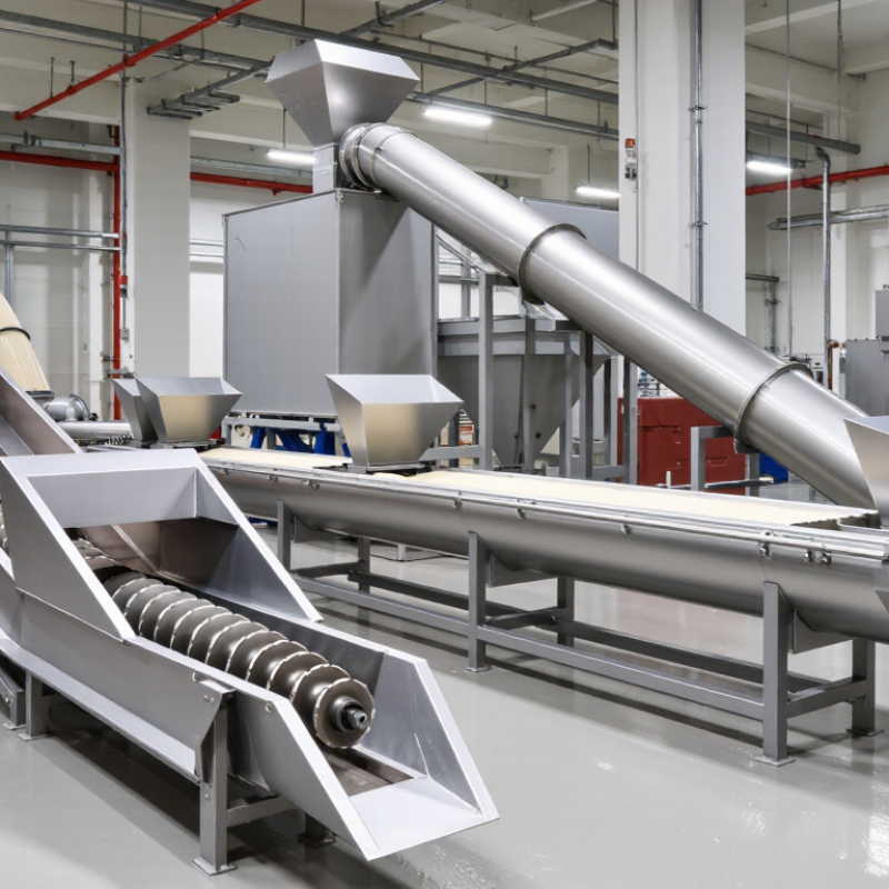
Choosing a powder screw conveyor is not simply a matter of selecting a diameter and motor. The right design depends on how the material flows, how far it must travel, and where the equipment will operate. Fine flour, dry minerals, and cohesive powders can behave very differently inside the same-looking conveyor. Some may bridge or compact; others may leak through small clearances or generate dust at transfer points.
Common options include tubular and U-trough screw conveyors, shaftless designs, vertical conveyors, and flexible screw systems. Each has practical trade-offs. A tubular unit can enclose material along its route, while a U-trough may offer easier access for inspection and cleaning. Shaftless systems can suit certain sticky or fibrous materials, but they are not automatically the best choice for every powder. Details matter. Inlet placement, screw pitch, operating speed, seals, and the condition of the feed can all affect performance.
This 2026 buyer’s guide compares powder screw conveyor types and the applications they may suit. It also highlights questions worth asking suppliers, including capacity assumptions, wear materials, maintenance access, and how test results relate to your actual product. A catalog chart is useful, but it cannot fully describe powder behavior. No layout is best in every plant; that point is easy to overlook. Treat specifications as a starting point, and confirm critical choices with material data or representative testing before purchase.
Powder Screw Conveyor Fundamentals: Capacity, Pitch, Speed, and Torque
2026 Top Powder Screw Conveyor Types for Buyers
Powder screw conveyor performance starts with capacity, not motor size. Capacity depends on screw diameter, pitch, rotational speed, bulk density, and trough loading. CEMA’s Screw Conveyors for Bulk Materials, 6th Edition, evaluates common loading cases at 15%, 30%, and 45%. Free-flowing powders may tolerate higher loading, while cohesive powders often need more space.
Pitch changes the conveyor’s behavior. A full pitch usually delivers higher capacity, but a reduced pitch can improve control near inlets or discharge points. Speed must match the powder’s flow pattern. Excessive speed can create aeration, segregation, or heat. A practical trial should observe a visible powder bed, not only a calculated rate. Small changes matter.
Torque protects the drive and shaft. The basic relationship is T = 9550P/n, where torque is in newton-metres, power is in kilowatts, and speed is in revolutions per minute. CEMA design methods also require attention to starting load, hanger friction, shaft deflection, and material buildup. A clean spreadsheet can still be wrong when moisture changes bulk density by 10% or more. Torque is the warning. Buyers should request test data using their actual powder, target rate, moisture range, and operating temperature. That evidence is more reliable than a catalog capacity alone.
2026 Top Powder Screw Conveyor Types for Buyers - Powder Screw Conveyor Fundamentals: Capacity, Pitch, Speed, and Torque
| Conveyor Type | Typical Configuration | Best-Suited Materials or Duty | Capacity Considerations | Pitch and Speed Guidance | Torque Considerations | Buyer Checks |
|---|---|---|---|---|---|---|
| Standard shafted screw | Helical flight around a center shaft; commonly installed in a U-trough or enclosed tube. | Free-flowing powders and granules, such as flour, cement, and plastic pellets. | Capacity depends on screw diameter, pitch, rotational speed, fill level, and bulk density. A larger diameter generally provides more capacity. | Standard pitch is often close to the screw diameter. Lower speeds are commonly preferred for abrasive or fragile products. | Check startup torque when the conveyor may start loaded, and account for bearing, seal, and material resistance. | Confirm material bulk density, particle size, abrasiveness, moisture, and required feed rate. |
| Tubular screw conveyor | Shafted screw operating inside a closed circular casing. | Enclosed transfer of dry powders where dust containment is important. | Capacity is affected by casing diameter, screw geometry, speed, inclination, and how consistently material is fed. | Pitch is commonly selected near the screw diameter for general conveying; speed should be checked against product degradation and wear. | Longer runs, bends, or loaded starts can raise the required torque; verify the drive for the complete duty cycle. | Review cleanout access, seals, inspection points, and compatibility with dust-control requirements. |
| Shaftless screw | Helical flight without a central shaft, supported by a wear liner or trough. | Sticky, cohesive, fibrous, or irregular material that may wrap around a center shaft. | Usable capacity varies with material behavior, liner condition, conveyor length, and operating speed. | Pitch and speed are selected for the material and installation; avoid assuming standard shafted-screw capacity ratings apply. | Can require substantial torque, particularly with cohesive material, long conveying distances, or a loaded restart. | Ask for material-specific test data and check flight, liner, and drive wear allowances. |
| Ribbon screw | Helical ribbon flight with openings between the flight and center pipe. | Cohesive or sticky powders where material buildup on a solid flight is a concern. | Capacity depends on ribbon geometry and material flow; it may differ from a solid-flight screw of the same diameter. | Choose pitch and speed based on flowability and mixing requirements, rather than diameter alone. | Evaluate resistance from compacted or sticky product and include loaded-start torque in drive selection. | Check cleanability, product carryover, and whether the application needs conveying, blending, or both. |
| Variable-pitch feeder screw | Flight pitch or geometry changes along the screw to draw material evenly from a hopper or outlet. | Metered feeding from bins, hoppers, and process vessels. | Designed for controlled, repeatable feed; actual rate depends on material head pressure, bulk density, and screw speed. | Variable pitch helps manage drawdown. A variable-speed drive is often used when feed rate must be adjusted. | Hopper pressure and compacted material can increase starting and operating torque near the inlet. | Confirm the required turndown, dosing accuracy, hopper outlet geometry, and any downstream interlocks. |
| Inclined screw conveyor | Shafted or shaftless screw installed at an upward angle. | Raising powders or granules between different process elevations. | Capacity is generally lower than for a comparable horizontal unit; the reduction depends on inclination and material flow. | Evaluate speed and pitch together with the angle. Material may slide backward or recirculate at steeper inclines. | Include the lift duty and any additional material hold-up when sizing the drive torque. | Specify the incline angle, vertical lift, material properties, and allowable feed-rate variation. |
Capacity, pitch, speed, and torque fundamentals: A first-pass volumetric capacity estimate for a horizontal screw is proportional to the usable flight area, pitch, rotational speed, and material fill factor. Mass capacity is the volumetric rate multiplied by bulk density. Increasing pitch or speed can raise theoretical capacity, but may also increase product degradation, wear, dust, or power demand. Required torque depends on material resistance, conveyor length and inclination, startup conditions, and mechanical losses. Values should be verified against the actual material and installation; there is no single capacity or speed that applies to every powder.
Related Posts
-
What Is a Powder Screw Conveyor and How Does It Work?
-
Why Choose a Horizontal Screw Conveyor for Bulk Handling?
-

2025 How to Choose the Right Screw Conveyor Auger for Your Needs
-
2026 Best Horizontal Screw Conveyor Options and Benefits?
-
Best Horizontal Screw Conveyor Solutions for Your Business Needs?
-
Top 10 Screw Conveyor Components for Efficient Material Handling?