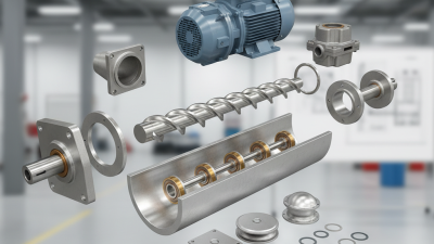
What Are the Top 10 Screw Conveyor Components?

A screw conveyor may look simple from the outside: a metal trough, a rotating shaft, and a steady flow of material. Inside, each part affects capacity, wear, safety, and maintenance. This guide examines the top 10 screw conveyor components, from the screw flight and shaft to bearings, trough, cover, drive, and seals. The details matter. A mismatched bearing or poorly chosen flight can turn routine operation into costly downtime.

The CEMA Screw Conveyor Engineering Committee is a respected technical authority in this field. A useful principle, paraphrasing its engineering guidance, is: “Choose components for the material and operating duty, not appearance alone.” That means considering particle size, abrasiveness, moisture, temperature, required capacity, and the conveyor’s layout. A dry grain-handling line and a system carrying damp, abrasive material may need very different component choices. The right answer is rarely universal.

The sections ahead explain what each component does, what to inspect, and where selection mistakes can occur. Look for practical details: flight shape, shaft alignment, bearing location, and access for cleaning. Small design differences matter. Still, component lists cannot replace a site-specific review, and this guide is no substitute for checking manufacturer specifications. That caveat is easy to overlook. Real installations vary, and even experienced teams sometimes discover that their original assumptions were wrong.
What Are the Top 10 Screw Conveyor Components?

How Screw Conveyor Components Work Together

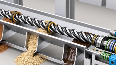
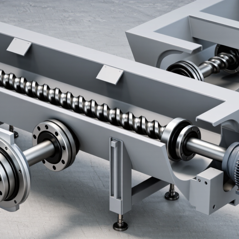
A screw conveyor works as a connected system, not a row of independent parts. The motor and gearbox turn the drive shaft; bearings support rotation, while the coupling transfers torque to the screw. Flights mounted on the shaft push material through the trough. The inlet controls where feed enters, and the outlet directs it onward. Small misalignments matter. A poorly supported shaft can rub the trough, wear the flights, and increase drive load. CEMA’s Screw Conveyors for Bulk Materials design guidance uses loading levels around 15%, 30%, and 45%, selected according to material characteristics. That range shows why component sizing must reflect the actual material, not just conveyor diameter.

Material behavior links every choice. Damp fines may cling to flights, while coarse particles can jam clearances; either can change flow and strain the drive. The cover helps contain dust, and seals limit leakage around rotating shafts. Keep inspection access practical. During checks, look for uneven flight wear, loose fasteners, hot bearings, and residue beneath seals. CEMA guidance offers useful design methods, but tables cannot fully capture lumpy feed or changing moisture. That gap deserves attention. A commissioning test with the real material can reveal surging, buildup, or motor loading that calculations miss. Recheck after process conditions change.

Powertrain Components: Motor, Gearbox, and Coupling

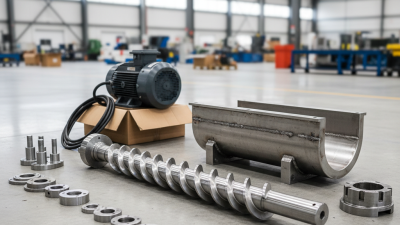
A screw conveyor’s motor, gearbox, and coupling must work as one powertrain. The motor supplies torque; the gearbox reduces speed and increases output torque. Select them for the material, throughput, screw diameter, incline, and starting load—not horsepower alone. A conveyor moving damp bulk material may need more starting torque than one carrying a steady, free-flowing product.

The U.S. Department of Energy’s United States Industrial Electric Motor Systems Market Opportunities Assessment estimated that motor-driven systems account for about 68% of U.S. manufacturing electricity use. That broad figure is not screw-conveyor-specific, but it shows why motor efficiency and correct sizing matter.

A gearbox ratio that runs the screw too fast can increase wear, while an undersized drive may struggle during startup. The coupling transfers torque and can accommodate limited misalignment; it cannot fix poor alignment. Check shaft fit, guarding, and vibration after installation. Small details matter. Sizing still involves judgment: actual material conditions often differ from design assumptions, so monitor current draw and temperature after commissioning.

Conveying Components: Screw Flighting, Shaft, and Trough

What Are the Top 10 Screw Conveyor Components?

Conveying Components: Screw Flighting, Shaft, and Trough

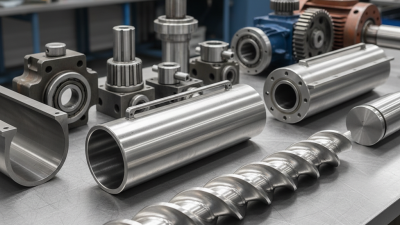
Screw flighting moves bulk material along the conveyor as the screw rotates. Its diameter, pitch, and shape affect capacity and material flow. Standard sectional flights suit many dry materials, while ribbon flighting can handle sticky products more effectively. Selection still depends on the material’s behavior; there is no universal flight design. Small gaps matter. Incorrect clearances may cause rubbing, accelerated wear, or material buildup.

The shaft supports the flights and transmits torque from the drive. Its diameter and material must suit the conveyor length, load, and operating conditions. A shaft that is too flexible can sag, changing clearances and increasing wear. Inspect welds and connections for cracks, especially near heavily loaded sections. A quick visual check helps, but it cannot reveal every alignment issue.

The trough contains and guides the material. U-shaped troughs are common, while tubular housings provide more complete enclosure. Covers can help control dust and protect conveyed material, but access for inspection and cleaning still matters. Check liners, joints, and discharge areas for wear or trapped material. Wear tells a story. Uneven marks may point to misalignment, poor clearances, or a process that needs review. The right arrangement depends on the product, throughput, and site conditions.

Material Flow Components: Inlet, Outlet, and Discharge Gate

At the inlet, material should enter the screw evenly, rather than fall onto one side of the flighting. A centered opening helps reduce uneven loading and unnecessary wear. For sticky or coarse material, the inlet size and shape matter: a narrow throat can bridge, while an oversized opening may overfeed the conveyor. Watch how material lands during startup. Small details matter. A short feed chute can also direct material toward the screw without creating a sudden pile. The best arrangement depends on the material’s flow behavior, not just its name on a specification sheet.

At the outlet, the discharge opening should clear material without leaving pockets around the casing. Its position and size affect how smoothly the conveyor empties. A discharge gate can isolate the outlet for inspection or help manage material release, but it should not be treated as a precise metering device. Screw speed and feed rate usually play a larger role. Not always obvious. Check that the gate moves freely and does not trap damp fines along its edges. In practice, a gate that looks adequate on a drawing can be awkward to clean or operate once installed. Regular inspection helps catch buildup, wear, and restricted flow before they disrupt material handling.

What Are the Top 10 Screw Conveyor Components?

Material Flow Components: Inlet, Outlet, and Discharge Gate

This chart groups ten common components by their primary function; the values are counts, not a ranking. Material-flow components: inlet, trough, screw flight, shaft, outlet, and discharge gate. Support and drive components: hanger bearing, end bearing, and drive unit. Enclosure component: trough cover. Actual configurations vary by conveyor design and application.

Support Components: Bearings, Hangers, and Seals

Support components rarely attract attention until a conveyor runs hot, leaks dust, or starts knocking. End bearings carry shaft loads, while hanger bearings support long screw sections inside the trough. Misalignment can create uneven wear; abrasive material can shorten service life. Small parts matter. During inspection, check bearing temperature, shaft movement, and grease condition. A clean exterior does not prove the internal bearing is healthy.

ISO 281:2007 defines L10 bearing life as the life that 90% of a group of identical bearings are expected to meet or exceed under stated operating conditions. It is a calculated rating, not a maintenance guarantee. Hanger bearings need suitable lubrication and enough clearance to avoid material buildup. Seals help keep dust out and lubricant in, but the right design depends on temperature, product characteristics, and cleaning conditions. CEMA’s Screw Conveyors for Bulk Materials also provides guidance on conveyor design and component selection. The practical detail is easy to miss: a seal that protects well may still complicate inspection. Review the actual operating conditions, not just the drawing.

What Are the Top 10 Screw Conveyor Components? — Support Components: Bearings, Hangers, and Seals

No. Component Primary Function Common Options Key Selection or Installation Consideration
1 End Bearing Assembly Supports the screw shaft at a conveyor end and helps maintain alignment. Mounted rolling-element bearing or plain bearing, selected for the application. Consider shaft loads, operating speed, temperature, contamination, and access for maintenance.
2 Hanger Bearing Supports the screw shaft between conveyor ends on longer or multi-section conveyors. Plain-bearing materials may include bronze, polymer, or other application-suitable materials. Material compatibility, lubrication needs, and product characteristics matter; the hanger can interrupt material flow.
3 Thrust Bearing Accommodates axial force generated during conveying and helps locate the screw shaft. Thrust-capable rolling-element arrangements or other engineered bearing assemblies. Locate and configure it according to the conveyor design and direction of axial loading.
4 Flange-Mounted Bearing Supports a shaft where the bearing is mounted to a flat plate or conveyor end structure. Two-bolt or four-bolt flange configurations, depending on the bearing design. Check mounting-surface stiffness, shaft alignment, load capacity, and sealing requirements.
5 Bearing Housing Holds and protects a bearing while providing a secure mounting interface. Cast or fabricated housings with suitable bearing and sealing arrangements. Allow adequate access for inspection and lubrication, and protect the assembly from dust or moisture where needed.
6 Hanger Bracket and Hanger Plate Connects an intermediate hanger bearing to the conveyor trough or cover structure. Bolted or welded supports designed for the conveyor configuration. Maintain the specified shaft centerline and provide clearance for the screw and conveyed material.
7 Compression Packing Seal Limits leakage and the entry of contaminants where a shaft passes through a housing. Adjustable packing rings compressed in a stuffing box. Requires appropriate packing selection and adjustment; excessive tightening can increase friction and shaft wear.
8 Lip Seal Helps retain lubricant and exclude dust or moisture around a rotating shaft. Elastomeric radial lip seals selected for the shaft and operating conditions. Confirm shaft finish, runout, temperature, speed, and compatibility with the process environment.
9 Labyrinth Seal Creates a non-contacting, tortuous path that helps reduce contaminant ingress or material escape. Single- or multi-path arrangements, sometimes combined with purge air where suitable. Performance depends on clearances and operating conditions; a labyrinth is not necessarily a pressure-tight seal.
10 Mechanical Shaft Seal Provides a close-running sealing interface for applications requiring greater leakage control. Single mechanical seal assemblies configured for the equipment and service. Selection may require review of shaft speed, temperature, pressure, product properties, and seal support needs.

Note: Component choice depends on conveyor geometry, material characteristics, operating conditions, and the manufacturer's design requirements. Confirm bearing loads, seal compatibility, and maintenance provisions for each application.